Wednesday 30 December 2009

Propshaft part 2 ... ready for the engine

Wednesday 30th December - Work time = 2hrs ... Build Time To Date = 76hrs
With the brakes fully functional I could now adjust the handbrake and torque up the bolts on the propshaft. 


I then set about "wrapping up" the chassis bars in the engine bay to protect them whilst installing the engine.   You can also see in the picture above a trapezium shaped peice of metal ... this is a gearbox adaptor plate but it is unclear in the manual whether I need to fit it for my engine/gearbox combination.  Need to do some reasearch!


Tuesday 29 December 2009

Bleeding Brakes ... easy with the Ezi Bleed !

Monday 28th December - Work time = 2.5hrs ... Build Time To Date = 74hrs
Armed with my Ezi Bleed system and 1.25 litres of Dot 5.1 Brake Fluid it was time to bleed the brakes.  This was not something I was particularly looking forward to as I had read many WSCC Forum posts and Build Diaries explain the pain and suffering caused by bleeding brakes on a Westfield. 
Following the various advice given and the Ezibleed instructions I set about the task.  I pressure tested the system with no fluid first at about 18psi and then filled the container with fluid, reduced the pressure to about 15psi and started bleeding each corner.  I managed to use all but about 350ml of Brake fluid.  I bled each corner twice just to be sure.  Disappointingly the pedal was still a little spongy so I decided to proceed with the Westfield method of pumping the pedal several times and then wedging the pedal down and leaving it overnight.


Another tip I read was to elevate the rear ... theory being that the air bubbes slowly rise.  So I enlisted Henry to lower the front onto the axles stands.  The front end being a little lighter than the rear I thought this would be an easy task for the pair of us.  Not so ... we got the front onto the axles stands and alarmingly the whole chassis starting sliding forwards (this gravity thing is a bloody nuisance!) until the rear was resting across the rear wishbones.  I then went to the rear and tried to shuffle the chassis back with Henry holding the front.  At this point the frame slid forward again and landed on Henry's foot.   We then reverted to the original configuration and put the front back on the build stand.  A quick look at the front chassis and fortunately there was no damage to the frame ... Henry meanwhile limped off to the house! 

I removed the wood prop this morning and was extremely pleased to see that overnight the "brake fairies" had spun their magic and the pedal was no longer spongy.  So moral of the story ... Ezi Bleed does what it says on the box and then leave it to a length of wood and the "brake fairies"!

Sunday 27 December 2009

Engine & ECU Loom ... getting bored with cable ties!

Sunday 27th December - Work time = 3hrs ... Build Time To Date = 71.5hrs
Fitted the engine and ECU looms today. To start with I needed to do the usual Westfield approach and remove some stuff I'd already fitted ! ... more precisely the main loom that I'd put in convoluted tubing and cable tied so neatly around the engine bay.  So what should have been a relatively short, simple job turned out to take 3 hrs.  It was worth the time though as it's all neat and tidy again.


Father Christmas lived up to expectations and delivered my Ezibleed system so it's brake bleeding time tomorrow ... wish me luck !

Wednesday 23 December 2009

Front Brake Pipes and ECU plate fitted

Wednesday 23rd December - Work time = 4.5hrs ... Build Time To Date = 68.5hrs
I spent about an hour and half sorting out the Webcon ECU wiring loom and Westfield engine wiring loom during the week.  The wiring diagram wasn't as good as the main loom and it didn't seem to completely match the actual wiring in the ECU loom?  So there was much head scratching again!  Finally got the looms all labelled ready for installation. 


Three hours spent in a rather cold garage today.  Got a few responses from the WSCC Forum on my handbrake adjustment issue.  Consensus was that I need to complete the braking system, fill it with fluid and then bleed the brakes to obtain a little pressure in the system to push out the caliper pistons and take up some of the slack.  So first job was to fit the flexible brake hoses on the front.  I had to complete the bends on the brake pipe ... I'd forgotten how difficult it was to bend the pipe!  Here's the completed job.


Now I need to get some brake fluid (Dot4) so I can start the bleeding!  This will have to wait a few days as I have heard that Father Christmas may be bringing me an EziBleed brake bleeding kit as recommended by various posters on the forum.
Next task today was to fit the ECU above the passenger footwell.  This took a little longer than expected as I fitted some rivnuts to the top fixing so it could be easily lowered for access (the manual suggested self tappers but I prefer the rivnut option)  The manual also said to mount the ECU on the plate with velcro.  I wasn't too happy with this option so found a couple of brackets and rivetted them to the plate and bolted the ECU to the brackets. The underside is fairly clear with just the rounded rivet heads as I'm sure the IVA test will be checking there is no sharp edges in the passenger footwell.  I'm quite pleased with the results.


Sunday 20 December 2009

Propshaft & Upper Steering Column ... well almost a propshaft

Saturday 20th December - Work time = 1.5 hrs ... Build Time To Date = 64 hrs
Next job on the list ... fit the propshaft.  A straightforward task ... 4 bolts, one propshaft, a torque wrench and some thread lock.  Hmm it's funny how the seemingly straightforward tasks turn out to be the the most difficult! 
The manual states that the prop can only be fitted and the bolts torqued when the handbrake is operational.  The handbrake was already fitted but I had failed to check that it was "fully operational" !  To cut a long story shorter the handbrake was not fully applying the pads to the discs so the wheels were spinning when I was trying to torque up the prop bolts.  After the usual head scratching I still couldn't figure why the handbrake wasn't clenching the pads enough ... perhaps there was some adjustment required to the calipers?  perhaps I need to fill the brake system and bleed the brakes first?  Hmmm a quick post of the Westfield forum to get some views seems required.
So with the prop now removed I turned my attention to the upper steering column.  This had arrived unexpectedly in the post the other day from Westfield.  They have had some issues with the original design resulting in a product recall so they held this part back when I collected the kit.  It was a bit fiddly to fit the column ... requiring a hole to be cut in the front bulkhead.  Lining up the position of the hole was tricky and because I didn't have a drill big enough I needed to expand the hole with a round file.  Unfortunately I got a bit carred away with the filing as the photos below show ... I'll need to get a suitably sized grommet to fill the gap!


So next step ... whilst I await a response from the forum re the handbrake adjustment ... is to sort out the ECU wiring loom and engine wiring loom.  More wires and more labelling!

Sunday 6 December 2009

Fuel Tank, Pump & Filter ... rear end almost complete

Sunday 6th December - Work time = 3.5 hrs ... Build Time To Date = 62.5 hrs
According to Westfield's estimated build duration I should now be halfway through having clocked just over 60 hours.  Things are progressing well but me thinks there is still more than 57.5 hours of work left!

Todays task to fit the fuel tank.  Before I started though I needed to finish a few outstanding jobs:
1.  Top up the diff with some more oil
2.  Finish covering the handbrake cables with convoluted tubing and secure to the wishbones.  Fortunately the eBay order arrived in the week so I could complete this task also.

Next job fit the fuel tank.  No issues with this ... just a bit fiddly to tighten the nuts securing the straps at the front ... there was not a lot of space between the tank and the rear bulkhead.  Fitting the fuel pump and filter were also a challenge.  After a bit of head scratching and consultation of a few build site photos I worked out the best options and routing for the pipes.  The fuel pump bolted through the rear chassis rail with a couple of spacers to push it away from the chassis rail and clear the left rear wishbone mount.
After drilling through the right hand diff chassis rail to fit the filter backet I realised that I didn't have any M6 bolts long enough to go through the rail ... doh!  So I fitted some M6 rivnuts instead ... will need to fill the unused holes on the over side somehow! 

Routing the fuel hoses was a little tricky too and I mdae a couple of attempts to fit the hose between the tank and fuel pump.  My first attempt looked good until I realised that when the car was on the ground and the suspension loaded that it would probably get trapped between the wishbone and the chassis!

I put convoluted tube over the full lengths of the hoses (I now have 5 metres of each size coutesy of my eBay order!).  This looks neater but I'm not sure whether the IVA inspector may need to see sight of the labelling on the hose to check that it's proper fuel hose ... may have to remove a bit of tubing at the test? 

At this point I must make a special mention for the huge contribution from both Sandra and Amy who popped in and out at various times this afternoon and acted as "drill trigger pusher" whilst I routed/held the flexible drill drive shaft to drill holes in various places for the cable tie mounts to secure the hoses.


I ran out of 5/16" hose to complete the filter to fixed fuel pipe connection.  Another trip to the motor factors!

Fuel Inertia Switch ... Fitted / Removed / Fitted Again!

Friday 4th December - Work time = 2 hrs ... Build Time To Date = 59 hrs
Just to set the scene ... it seems a common practice to fit things ... flick a few pages forward in the manual ... and then find you need to remove it again to fit something else. 
I fitted the inertia switch one evening this week.  A fairly simple task ... a couple of holes in the bracket behind the diff.   As always I stood back to admire the work.


It was then just a case of tidying up the wires once the fuel pump was installed.  However a couple of days later I read forward in the manual and the build photos showed the inertia switch on the other side!  Off with the switch and back on again, this time on the correct side.  The change meant I also needed to reroute the wiring loom to the front side of the chassis rail ... removal of more cables ties!


I then spent the rest of the time sorting out the various bits and pieces ready to fit the fuel tank, fuel pump and fuel filter.  A job for the weekend !

Monday 30 November 2009

Drive Shafts and Hand Brake ... a completed drive train

Monday 30th November - Work time = 4.5 hrs ... Build Time To Date = 57 hrs
Having carefully bolted together the rear suspension it was now necessary to unbolt the top hub to wishbone linkage to fit the drive shafts.  I seem to be bolting / fixing things on only to take them off a couple of chapters later in the build manual!
Fitting the drive shafts was a bit fiddly while trying to get the set screws in (with loctite thread lock on) ... however my very expensive hex sockets worked miracles again ! ;-) and both shafts were quickly torqued up on the hubs and diff.

I quickly filled the diff with EP80w/90 oil ... although the 1 litre which Westfield had provided didn't completely fill up the diff to the fill level so I need to get some more ... another job on the list !
With the rear suspension and drive train completed I flicked over to the next chapter in the manual ... hand brake and rear flexible brake pipes.  Connecting up the cabes to the hand brake lever was a bit awkward requiring lots of winding of the adjuster.  Also I ran out of the convoluted tubing that Westfield had provided to cover the cables where they touched the metalwork.  A quick look on eBay and more was ordered ... another job to finish off later.  Here's a few pictures of the hand brake in situ and the cable routing.


Rear Discs and the Diff ... not as difficult as I feared

Sunday 29th November - Work time = 4 hrs ... Build Time To Date = 52.5 hrs
With my (rather expensive) 3/8" to 1/2" socket drive adaptor and the hex sockets I could continue with fitting the rear discs and calipers.  No problems with fitting these ... probably due to the expensive hex sockets no doubt!


Next step ... fit the diff !  Hmm it's a bit heavy so time to enlist some muscle (aka Henry!).  As it turns out it was a lot easier than I thought it would be.  As instructed in the manual I pushed the threaded bars through from the right hand side.  I removed the offside brake line to provide a bit of room.  Apart from just a few issues with slotting in the washers between the diff and the bushes on the left hand side it was pretty straightforward. 


Tuesday 24 November 2009

Front & Rear Hubs on ... 4 wheels on the wagon (almost)

Tuesday 24th November - Work time = 3 hrs ... Build Time To Date = 48.5 hrs
Another day off ! But a good excuse ... Henry's 16th Birthday (Hippo Bird day H !) and Amy was playing the drums at a school concert (Rock on Amy !).  In between these I managed to do some work on the car.
Firstly fitted the front hubs ... the only issue was tightening the nut on the top ball joint.  It needed a lot of downward pressure to stop it revolving.  Got there in the end.  Here's the finished article.


I then moved to the rear suspension.  All was pretty straightforward and I soon had the hubs on both sides.  Standing back to admire my work I checked the manual for the next step ... trouble was the picture in the manual didn't match what I had built.  "Oh bother" I exclaimed (or words to that efffect) ... I had put the lower wishbones on the wrong way round ... on both sides!  The manual clearly states the single arm with the bush at the front ... I had it at the back.  Here's the wrong way and the right way once I'd taken both sides off and started again.


And here is a photo of both sides completed.


Next step to fit the rear discs and calipers.  I realised I couldn't start this as I hadn't got any hex sockets for the set screws that secure the calipers to the hubs.  I needed two different sizes, one for the calipers and one for the driveshafts.  A trip to the local motor factors and £37 later (don't tell Sandra) I had a full set of 3/8" drive hex bits with a 1/2" adaptor so that I could connect them to the torque wrench.  All sorted ready for the next build session!

Sunday 22 November 2009

Front Suspension ... time for the spanners!

Sunday 22nd November - Work time = 2.5 hrs ... Build Time To Date = 45.5 hrs
Fitted the front wishbones, shock absorbers and steering rack today.  Just a few little issues to contend with. 
As I mentioned in the last post I was missing the headlamp brackets which bolt together with the upper wishbones.  However when the replacements arrived from Westfield they looked identical to a couple of other brackets I already had but were completely different to how they looked in the manual?  I flicked forward in the manual to the supplemental section covering the FW bodywork and lo and behold because I was having the FW bonnet the headlamp brackets were different to those described in the suspension section of the manual ... make note to self - read the manual front to back again!
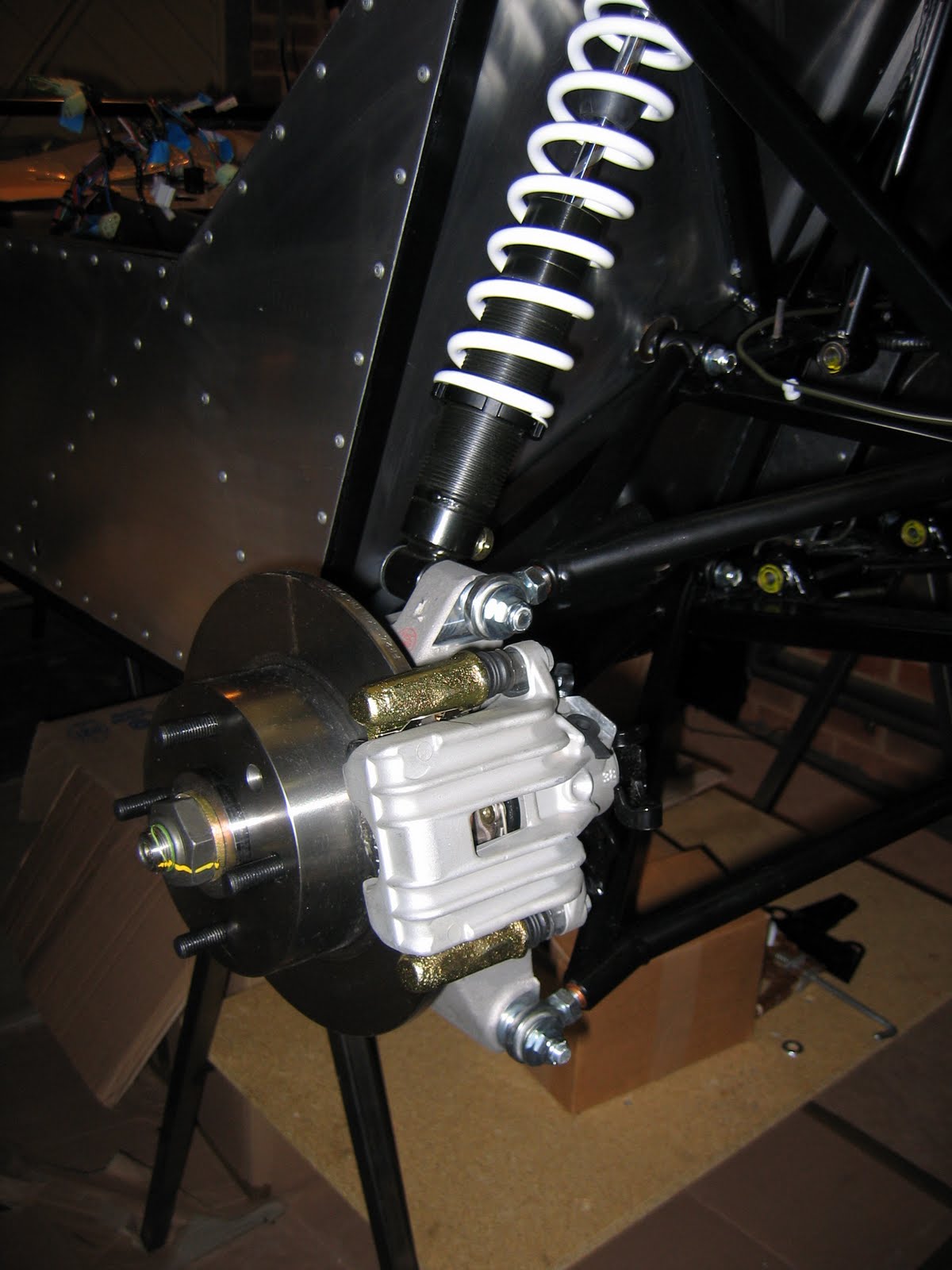
Everything else on the front suspension was pretty straightforward.  As detailed in the manual all the main bolts were just "nipped tight" to be torqued to the specified settings when the car is loaded on it's wheels.  A few bolts were able to be tightened ... bottom ball joints and steering rack mounts.  I painted a red line (Alfa red touch up paint from my old 147 GTA !) on the nuts to signify they were tight and torqued to the right settings.
A couple of pictures of the front suspension fitted ... it's starting to look a bit more car like now.  Next step ... fit the front hubs.


Monday 16 November 2009

Exterior Panels fitted ... an end to the rivetting

Sunday 15th November - Work time = 2.5 hrs ... Build Time To Date = 43 hrs
Finally fitted the two exterior side panels today.  I had drilled the chassis previously so it was a fairly simple job.  I even managed to get Sandra to put in one of the rivets ... she commented that it was "hard work and didn't enjoy it much!"

Here's a couple of pictures showing the hedgehog before and completed after.


I spent the rest of the time sorting out the parts ready to start installing the suspension (I get to use the spanners again !)  Couldn't find any headlamp brackets that are bolted onto the front wishbones so I'll have to make another call to Westfield parts dept before I can start.

Saturday 14 November 2009

Wiring ... installation

Saturday 14th November - Work time = 7.5 hrs ... Build Time To Date = 40.5 hrs

I spent a couple of hours during the week sorting out and labelling the loom.  It took a little while to interpet the wiring diagram.


The labelling was a slightly tedious task but proved to be well worth the effort when I came to the installation.  Henry captured the labelling task and as a result of his creative photography skills he managed to show me wearing the lamp shade ... thanks H ! 


Before I started installing the loom today I wanted to add a couple of extra power feeds for the intercom and brantz rally meter.  I added these to the Power Socket/Horn/Hazards circuit which was wired back to a 20amp fuse in the fuse box so should be OK.  This was a pretty straightforward task although it needed a lot of insulation tape to bind the new wires into the loom.

So to the installation ... first step install the fuse boxes ... so far so good.  Then it was a case of pulling the wires for the dash instruments, switches, warning lights etc through the transmission tunnel front panel into the cockpit.  It looked like a big hole in the transmission tunnel panel when I started but it quickly filled and there was a lot of pushing and pulling to get all the cables and connectors through.  The relays were particularly difficult ... I contemplated taking them apart but finaly managed to get them through after pulling back some of the other wires to create some more space.


It took a long time to route the front and rear parts of the loom and I had to install a lot more cable tie fixings to keep the wires tidy.  At the rear the instructions say to double back the loom from the offside rear corner back to the nearside rear corner.  I didn't complete this bit as I'm sure that there will be things like the fuel pump and regulator mounted across the back so I might end up having to reroute the wires later once I have these installed.


I'm pleased with the finished loom installation ... only time will tell whether everything still works !

Tuesday 10 November 2009

Wiring ... getting ready to run the loom

Monday 9th November - Work time = 4 hrs ... Build Time To Date = 33 hrs
A day off work today so I can crack on with the build.  Firstly good news ... managed to fix the printer last night so Sandra is happy again!
So today's schedule of work ... start Chapter 3 of the Build Manual ... entitled Wiring Loom.  Firstly attach the fixings for the wiring loom ... yet more drilling.  I had originally bought 20 x 4.1 mm drills off eBay for the rivet hole drilling ... for each stint I was using a fresh new one so I am pleased I got plenty.  
First issue was the chassis was the right way up on the stands and it appeared that most of the clips were on the lower chassis bars ... hmmm slight issue as all my trainee mechanics were at school!  Three Shredded Wheat later I managed to turn the chassis over by myself.  The only other issues were some of the awkward places at the front where it was dfficult to get the drill into.  A combination of normal drill, flexible drive attachment and hand drill prevailed eventually.  Also when I got to the rear it was not clear in the manual where to place the clips on the offside ... the manual merely shows 4 on the outer rail but mentions in the loom routing instructions that it "loops back from the other corner" but it is not clear using what route? Oh well when I get the wires in place it will probably be a bit more apparent.
Here's a few more pictures ... progress is not that apparant but if you look caefully you can see the loom fixings ... there's about 40 there somewhere!


Having finished the fixings I flipped the chassis back over to fit the scuttle panel and the first part of the transmission tunnel panel.  I decided to shorten the transmission panel and cut it across the first brace.  This would allow me more access when routing the cables.  I plan to rivnut fix all the other transmission panels for ease of access in the future.  Talking of rivnuts ... I got the chance to use my new rivnut tool and fitted 4 x M4 rivnuts for the fuse box attachment ... this makes fitting and removal easier than a bolt and a loose nut.


Next step, start sorting out the loom and labelling the various parts.  Hmmm this may take a little time!